The examples of parametric functions shown here are just a selection from the entire spectrum, roughly sorted by trade.
The large number of standard bocad functions are not shown here.
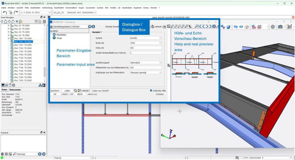
The individual dialogue boxes for the functions are not shown here. One dialogue box is explained at the end of the list as an example.
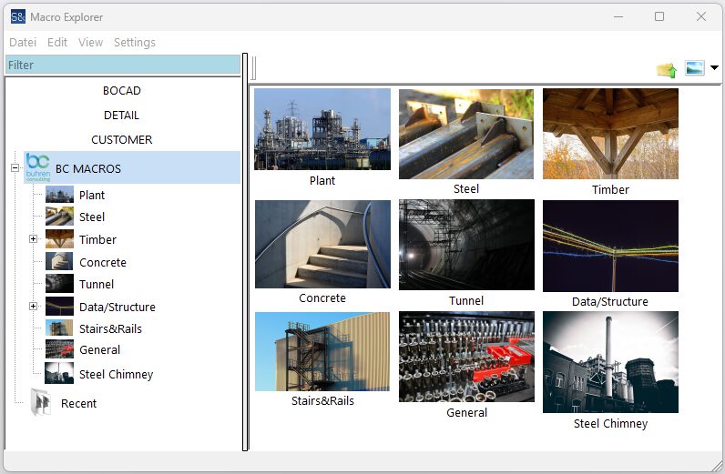
Plant Steel Construction
Description of the examples
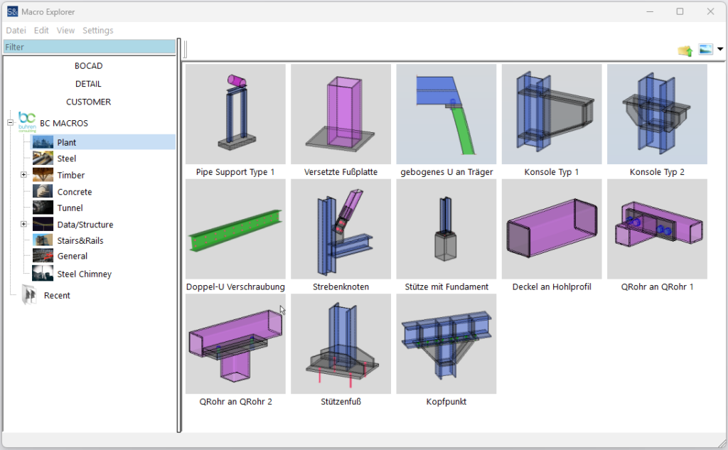
- ‘Pipe Support Type 1’ creates complete support structure with fasteners based on load types. The foundation and pipe are picked.
- ‘Offset base plate’ produces base plate according to specified dimensions with weld. The column is picked.
- ‘Curved U to beam’ creates a bolted connection with end plates between a curved U-beam and an I-profile. The I-profile and U-beam are picked.
- ‘Bracket type 1’ creates a complete single-sided bracket construction with weld seams. The support and 1 height point are picked.
- ‘Bracket type 2’ creates a complete double-sided bracket construction with weld seams. The support and 1 height point are picked.
- ‘Double U screw connection’ screws 2 adjacent U-profiles together. The two U-profiles are picked.
- ‘Strut node’ creates the complete node with screws and seams. Column and transom are picked.
- ‘Column with foundation’ creates a column with connecting parts and single foundation. Only the position point is picked.
- ‘Cover on hollow section’ creates covers on hollow sections with weld seam on both sides. The pipe is picked.
- ‘QTube to QTube 1’ creates a bolted connection between 2 hollow sections. The two hollow profiles are picked.
- ‘QTube to QTube 2’ creates a screwed connection between 2 hollow profiles. The two hollow profiles are picked.
- ‘Column base’ creates a column base on a steel column with fasteners. The steel column is picked
- ‘Head point’ creates a head connection with fasteners. The steel column and transom are picked.
Steel Construction
Description of the examples
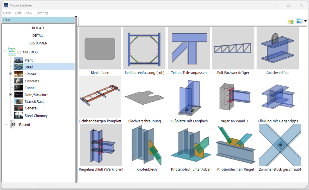
- ‘Plate bevelling’ bevels all 4 corners of rectangular sheets. The rectangular sheets are picked.
- ‘Container surround (raw)’ creates the necessary beams for a container surround. The two main beams and 2 position points are picked.
- ‘Adapt part to parts’ adapts the end face of a part to several other parts. All parts involved are picked.
- ‘Console truss girder’ creates a complete truss girder with connections. The start and end points are picked.
- ‘Weld-on eyelet’ creates a weld-on eyelet on a beam with a seam. The beam and 2 position points are picked.
- ‘Complete continuous rooflight frame’ creates the continuous rooflight frames according to manufacturer with all edge plates, brackets and horizontal braces. Beams and position points are picked.
- ‘Plate metal screw connection’ creates self-drilling screws at the edges. The contour plates are picked.
- ‘Base plate with slotted hole’ creates a base plate on a column with connections. The column is picked.
- ‘Beam to wall 1’ connects a beam to the end face of a concrete wall. The beam and wall are picked.
- ‘Notching with counter rib’ notches one beam into another and creates a rib with seams on the opposite side. The two beams are picked.
- ‘Transom connection (factory standard)’ connects a transom to a column. The transom and column are picked.
- ‘Gusset plate’ creates a gusset plate between the column and L-profile. Column and L-profile are picked.
- ‘Gusset plate bottom/top’ creates gusset plate on 2 parts and L-profile. The 3 parts are picked.
- ‘Gusset plate on transom’ creates a gusset plate on the transom of 2 L-profiles. L-profiles and transoms are picked.
- ‘Screwed spacer’ creates a spacer between 2 L-profiles. The L-profiles are picked.
Timber Construction
Description of the examples
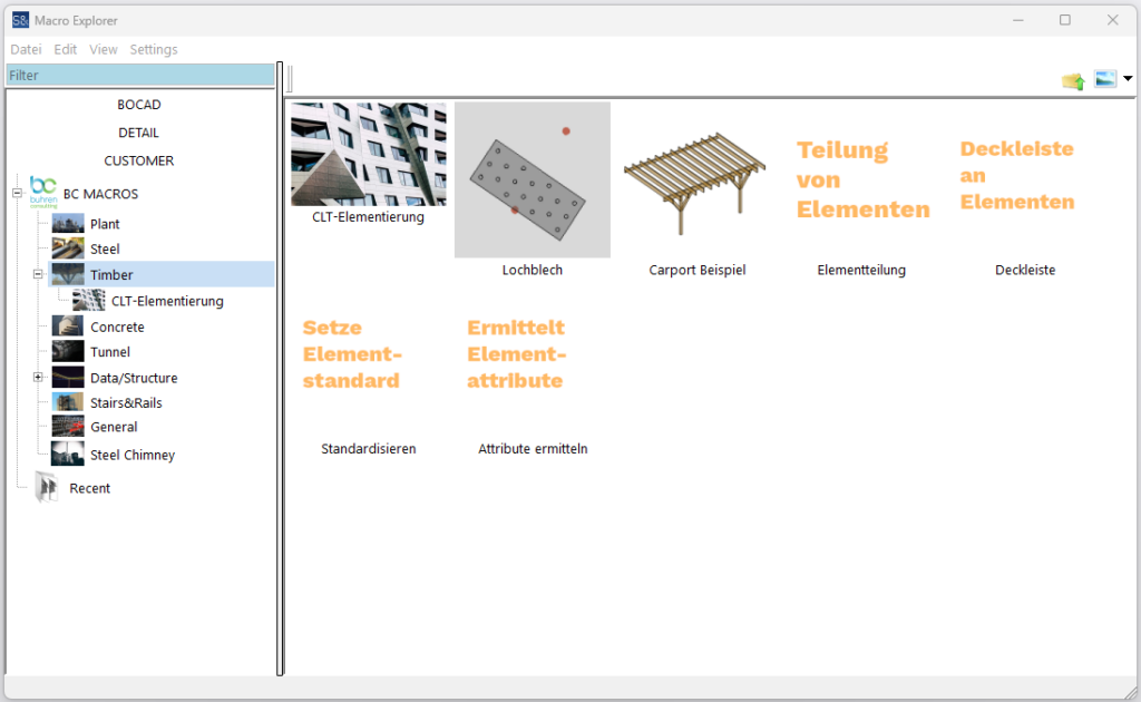
- ‘Perforated sheet’ creates a standardised perforated sheet. Two installation points are picked.
- ‘Carport example’ creates a complete carport without connection details. 2 position points are picked.
- CLT elementisation (Cross Laminated Timber)
- ‘Division of elements’ creates a CLT element division from a large plate.
- ‘Cover moulding on elements’ creates cover mouldings between the elements.
- ‘Set element standard’ turns normal parts into CLT elements.
- ‘Determine element attributes’ prepares the element-specific data so that it can be output on drawings and parts lists.
Concrete
Description of the examples
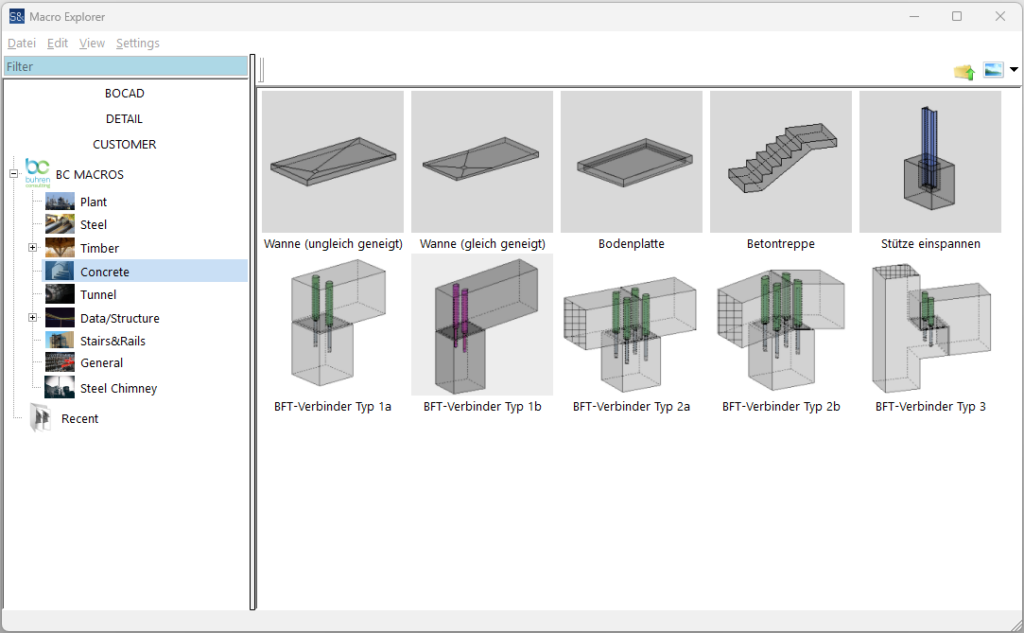
- ‘Tray (unequally inclined)’ creates a drainage tray from an existing concrete part. Reference points are picked.
- ‘Tray (equal slope)’ creates a drain tray from an existing concrete part. Reference points are picked.
- ‘Floor slab’ creates a floor slab with a surrounding concrete strip. The contour points are picked.
- ‘Concrete staircase’ creates a concrete staircase. Two position points are picked.
- ‘Clamp column’ creates a single foundation on a column and creates an anchor plate. The column is picked.
- ‘BFT connector type 1a’ creates a dowel connection between 2 precast concrete elements with corrugated sheathing pipes, dowel sleeves and elastomer bearing. The two parts are picked.
- ‘BFT connector type 1b’ creates a dowel connection between 2 precast concrete elements with corrugated sheathing pipes, dowel sleeves and elastomer bearing. The two parts are picked.
- ‘BFT connector type 2a’ creates a dowel connection between 2 precast concrete elements with corrugated sheathing pipes, dowel sleeves and elastomer bearing. The two parts are picked.
- ‘BFT connector type 2b’ creates a dowel connection between 2 precast concrete elements with corrugated sheathing pipes, dowel sleeves and elastomer bearing. The two parts are picked.
- ‘BFT connector type 3’ creates a dowel connection between 2 precast concrete elements with corrugated sheathing pipes, dowel sleeves and elastomer bearing. The two parts are picked.
Tunnel
Description of the examples
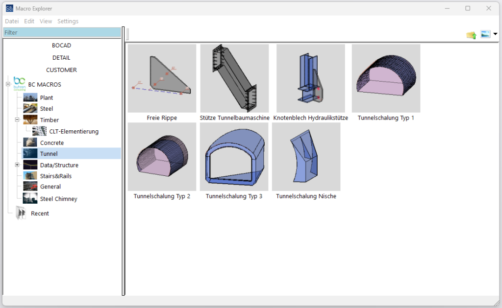
- ‘Free stiffner’ creates a special stiffner shape on heavy steel beams. Reference points are picked.
- ‘Support tunnelling machine’ creates an inclined support with stiffeners and seams. The upper and lower connection points are picked.
- ‘Hydraulic support gusset plate’ creates a standard gusset plate for hydraulic supports on any beams. The connection beams are picked.
- ‘Tunnel formwork type 1’ creates the curved tunnel formwork for cross-section type 1. Reference points are picked.
- ‘Tunnel formwork type 1’ creates the curved tunnel formwork for cross-section type 2. Reference points are picked.
- ‘Tunnel formwork type 3’ creates the curved tunnel formwork for a cross access. Reference points and main formwork are picked.
- ‘Niche tunnel formwork’ creates the formwork for an equipment niche. Reference points and main formwork are picked.
Data/Structure
Description of the examples
- ‘Group phases’ creates project type-related phases as a working structure.
- ‘IFC linker’ links drawing names with model parts and writes these as a path in the IFC. This ensures that the drawing is displayed directly when clicking on a part in the BIM viewer.
- ‘BMF-Renamer’ renames drawings in batches in relation to their content. This allows self-defined descriptive names to be achieved, which makes further processing considerably easier.
- ‘Template Drawings’ assigns a template drawing to any drawing, on which certain parameters such as number of pieces or length are then automatically adjusted.
Stairs & Rails
Description of the examples
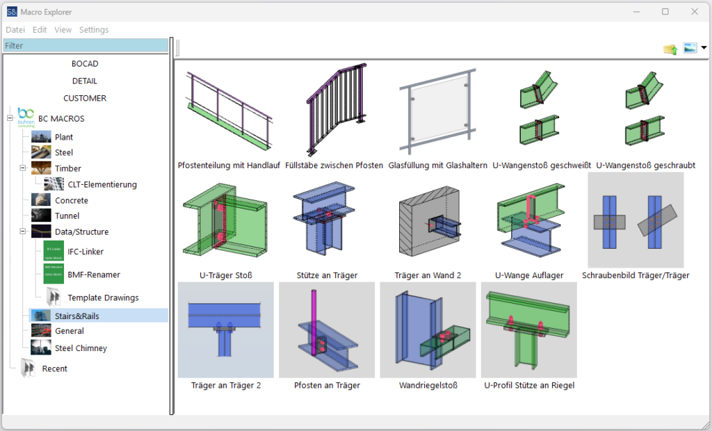
- ‘Post division with handrail’ creates the handrail with post division and optional top and bottom rail on an existing stringer. The stringer beams are picked from bottom to top.
- ‘Filler bars between posts’ creates a division with filler bars between 2 posts and optional top and bottom chord. The mullions and the bordering parts are picked.
- ‘Glass infill with glass holders’ creates arbitrarily shaped glass infills with glass holders according to the manufacturer. The surrounding points are picked.
- ‘Welded U-joint’ creates a welded cheek joint with seams. The two beams are picked.
- ‘U-joint screwed’ creates a welded cheek joint with fasteners. The two beams are picked.
- ‘U-beam joint’ creates a bolted joint. The two beams are picked.
- ‘Column to beam’ creates a bolted head connection. The support and beam are picked.
- ‘Beam to wall 2’ creates a simple end connection to a concrete wall. The beam and wall are picked.
- ‘U-profile support’ bolts an overlying U-profile to the beam and inserts a stiffener. U-profile and beam are picked.
- ‘Beam/girder screw pattern’ screws 2 superimposed beams together. The two beams are picked.
- ‘Beam to beam 2’ creates a screw connection of a beam to the flange side of a beam. The two beams are picked.
- ‘Post to beam’ connects a railing post screwed with a stiffener to a beam. Mullions and beams are picked.
- ‘Wall transom joint’ connects 2 abutting wall transoms screwed to a column. The wall transoms and the column are picked.
- ‘U-profile column to transom’ connects 2 U-profiles to each other. The two beams are picked.
General
Description of the examples
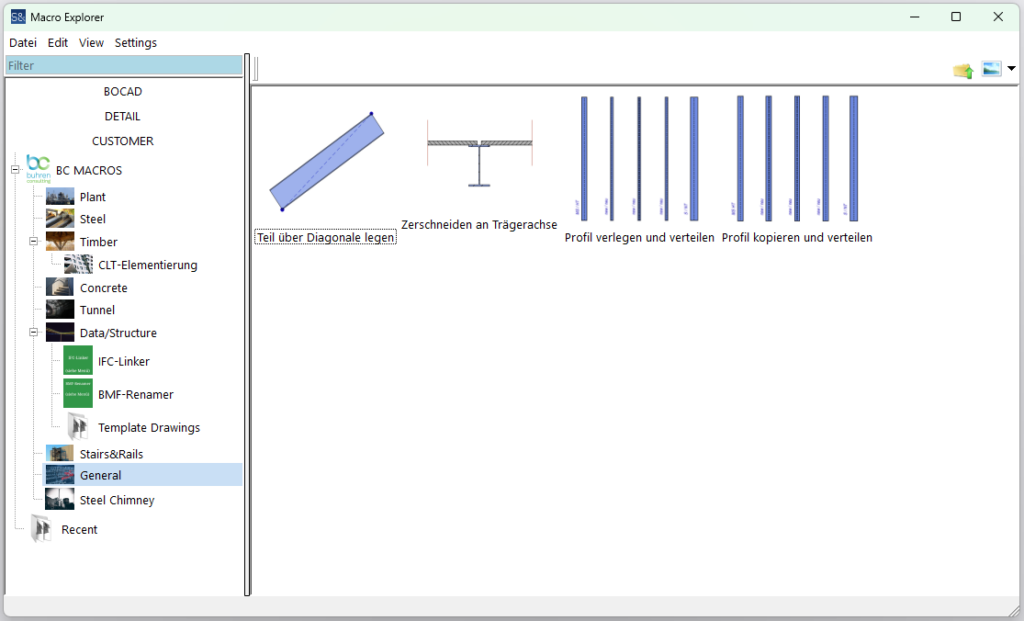
- ‘Place part over diagonal’ creates a profile over its own diagonal. Two laying points are picked.
- ‘Cut along beam axis’ cuts sheets along the centre axis of the underlying beam. The sheets and the beam are picked.
- ‘Lay and distribute profile’ creates an even distribution of profiles with the same clear dimension between any beams. The limiting beams are picked.
- ‘Copy and distribute profile’ evenly copies a profile with the same clear dimension between any beams. The limiting beams are picked.
Steel Chimney Construction
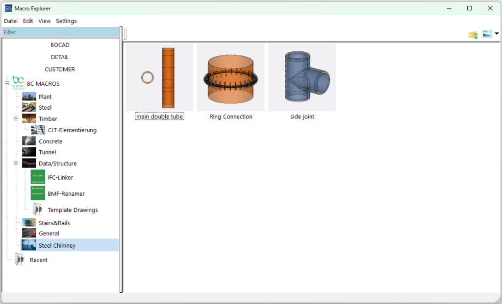
Description of the examples
- ‘main double tube’ creates a two-layer chimney with different element sizes, such as a 30 metre high chimney with 2.50 metre elements on the outside and 1.50 metre elements on the inside, including intermediate insulation. The centre point is picked.
- ‘Ring Connection’ connects 2 outer chimney elements via 2 rings with ribs, screws and seams. Two chimney elements are picked.
- ‘Side joint’ creates a side connection to the chimney for the outer pipe, inner pipe and insulation and creates the connection contours for the weld seam. The chimney elements and 2 height points are picked.
Example dialogue box in the bocad user interface

![[:de]Buhren Consulting[:]](https://buhren-consulting.com/wp-content/uploads/2019/09/cropped-horizontal_print-1-1.png)